



At a glance
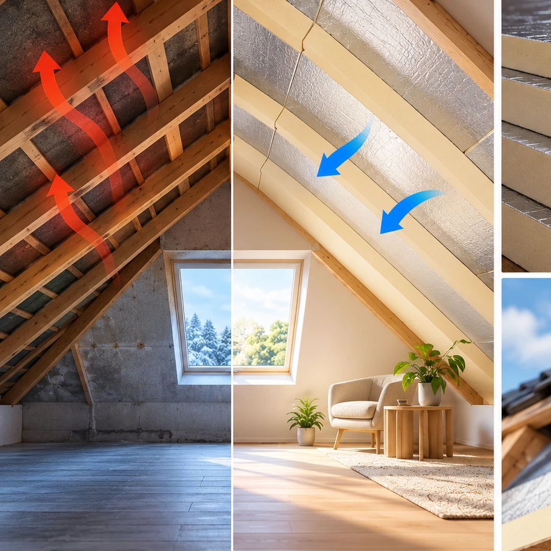
PIR thickness for a heated attic roof depends on the actual board and the complete roof construction. The source comparison considered 140–180 mm boards with a declared conductivity of 0.022 W/(m·K), particularly in a continuous above-rafter layer. These are design examples, not a universal minimum or a guarantee that 160 mm will suit every roof. Rafters, fixings, joints, roof windows and other layers affect the result. This guide explains the resistance figures, compares above-rafter and between-rafter installation and shows why the designer must confirm the complete roof rather than select insulation from thickness alone.

Are PIR and PUR the same?
PIR and PUR belong to the broader polyurethane-family insulation group but have different chemical structures and formulations. PIR is commonly supplied as factory-made rigid boards; PUR is also used in site-applied spray systems. Rigid PUR products exist too, so the material name and installation method are not interchangeable.
Check the exact product declaration, facing and intended use. A general foam description does not establish conductivity, moisture behaviour or fire performance.
Compare fire evidence for the actual construction
PIR can behave differently from conventional PUR under heat, but broad chemical explanations do not establish a universal ranking for flame spread, smoke or fire resistance. Compare the relevant tested products and complete roof assemblies.
Neither material name alone proves that a required roof classification is met. Follow the project’s documented fire-protection requirements.

Comparing the thickness examples
At λD=0.022 W/(m·K), the source used approximate declared resistance examples of 6.35 m²K/W for 140 mm, 6.80 for 150 mm and 7.25 for 160 mm. These are rounded product-style examples; the actual declared value must come from the board documentation.
Within the same product family, 160 mm provides more resistance than 140 or 150 mm, and 180 mm provides more again. This does not make 160 mm a universally safe standard or prove that the thinnest option always fails.
Assess the complete roof
The source compared heated-roof designs with Uc≤0.15 W/(m²·K) in its Polish context for rooms at least 16°C. Treat this as the stated comparison target and confirm the applicable requirements for the actual project and location.
The calculation should include the insulation, rafters, decking, internal lining, relevant air layers, membranes, mechanical fixings and junctions at the wall plate, ridge and roof windows. A heat pump does not by itself set the required insulation thickness.

140, 150 or 160 mm?
A U-value of 0.15 W/(m²·K) corresponds to a simple total resistance of about 6.67 m²K/W before considering how the complete calculation is performed. A board’s resistance is only one part of that calculation. Corrections, surface resistances and thermal bridges must not be ignored.
140 mm at the stated conductivity can be a marginal option in some designs. 150 mm may be sufficient in a suitable continuous above-rafter construction, while 160 mm offers more resistance. None of these statements replaces the project calculation.
A complex roof, many openings, discontinuous insulation or a different conductivity can change the outcome. Conversely, other existing layers can contribute resistance. Consider long-term use and the difficulty of future improvements alongside initial cost.
Continuous insulation above the rafters
An above-rafter layer reduces the interruption of insulation by timber. Depending on the project, it can retain visible rafters, avoid reducing attic space and allow some existing internal finishes to remain.
Refurbishment may require removal of the covering and careful eaves, ridge and roof-window details. Tongue-and-groove edges are available on some suitable products, but do not replace complete joint and air-control detailing.
Insulation between the rafters
Between-rafter boards can be considered for work from inside. Accurate cutting and fitting are important, and the timber interrupts the insulation layer. A continuous additional layer above or below can reduce that effect.
The source gave an example of 100–120 mm between rafters plus 40–60 mm below. This is not a ready-made design: rafter dimensions and spacing, product properties, fixings and vapour-control layers determine the suitable arrangement.
Confirm roof ventilation and moisture details before work starts. Select the thickness and position as part of one roof system.
Ask about materials for your project
Tell us which material you need, the quantity and delivery location. The SteelProfil team will help prepare an offer for your inquiry.
Phone: +48 500 409 109
REQUEST A QUOTE!


